PLANNING A CONNECTICUT REMODEL
Architectural Plans vs. FHC Working Plans: A Visual Guide
A floor plan can show where your new kitchen goes. The people building it also need to understand the cabinet sizes, appliance openings, installation heights, electrical locations, and details where the new work meets the existing home.
That is the difference we want homeowners to see when we talk about architectural plans and our working plans: the overall design, followed by the job-specific information that helps our team carry it out. The examples below show actual drawing excerpts, rather than asking you to imagine the difference.
See the difference in the drawings
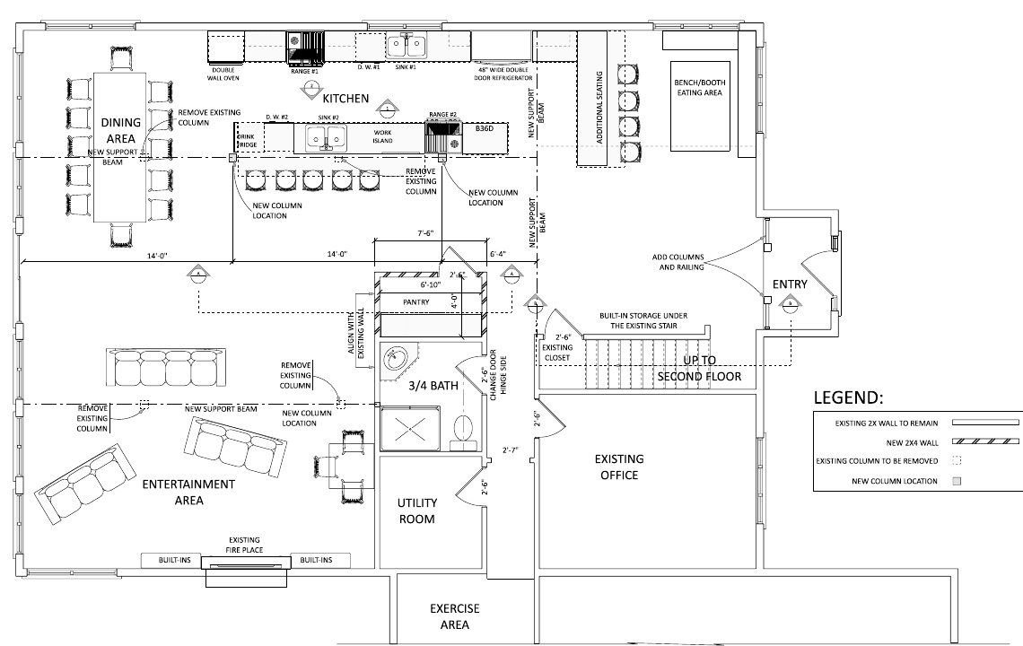
These two excerpts come from the same remodeling project. The conventional 2D layout communicates the arrangement of the rooms. FHC’s kitchen working sheet adds multiple dimensioned views of the cabinetry, with references connecting the plan to its elevations.
Conventional 2D layout
FHC kitchen working sheet
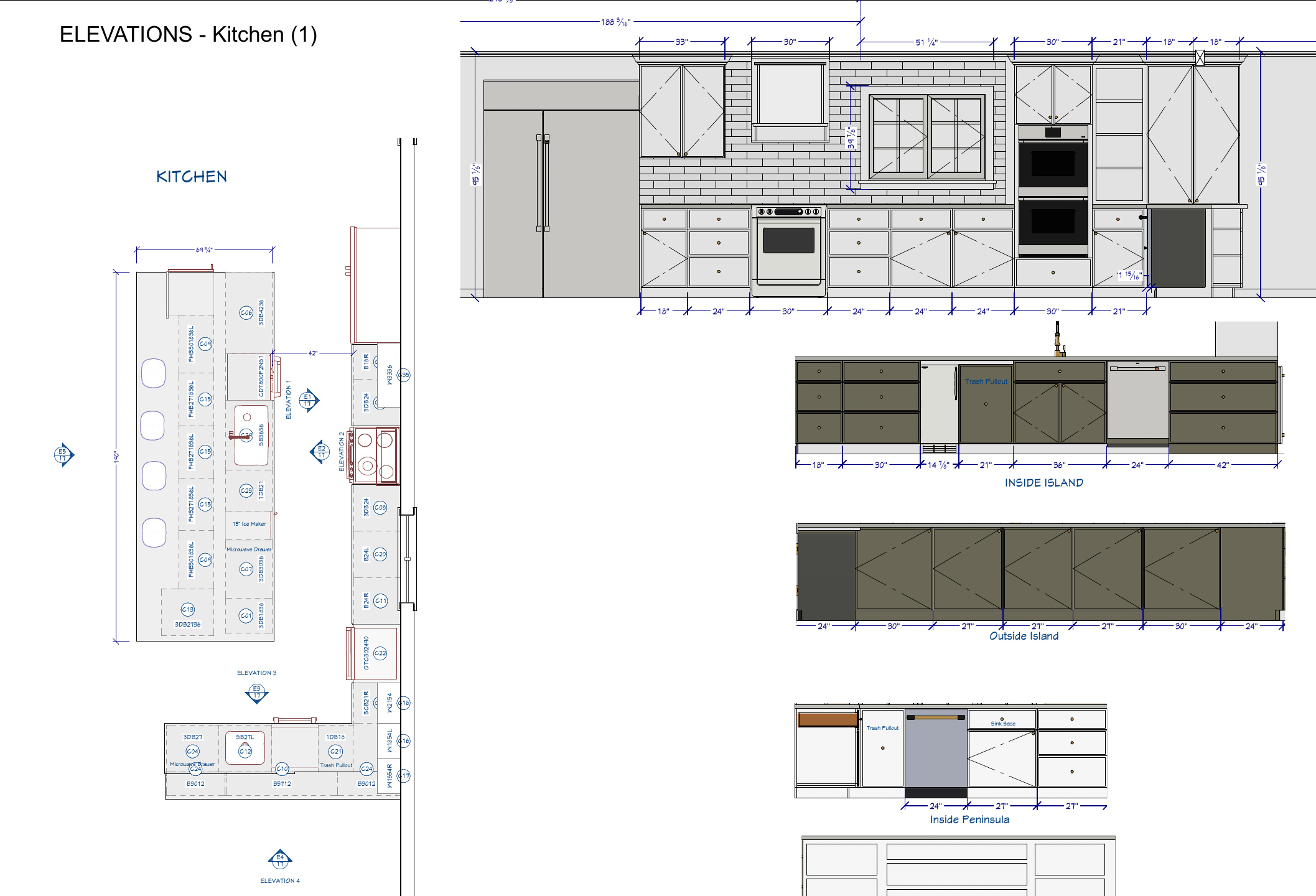
Select a drawing to enlarge it. These are different sheet types and revision stages from one project, shown to compare presentation and detail. Client names and addresses have been removed. The 2D excerpt is a conventional design drawing supplied on the job; it is not presented as proof of any architect’s complete scope or missing work.
Why an overall layout can be hard to build from on its own
Technical drawings use symbols, line types, dimensions, and references to other sheets. An experienced builder reads those conventions, but a homeowner may have difficulty picturing the finished space from an overhead view.
There is also a practical difference between understanding the layout and having the details needed for a particular installation. A cabinet shown on a floor plan still needs a size and configuration. A wall light needs a coordinated position. A recessed cabinet needs space inside the wall.
When those decisions are not resolved in the supplied documents, the building team needs further details or clarification. That can mean more conversations, revised drawings, or decisions during construction. Our working drawings are intended to bring that information together for the work our team is carrying out.
Dimensions you can connect to the finished room
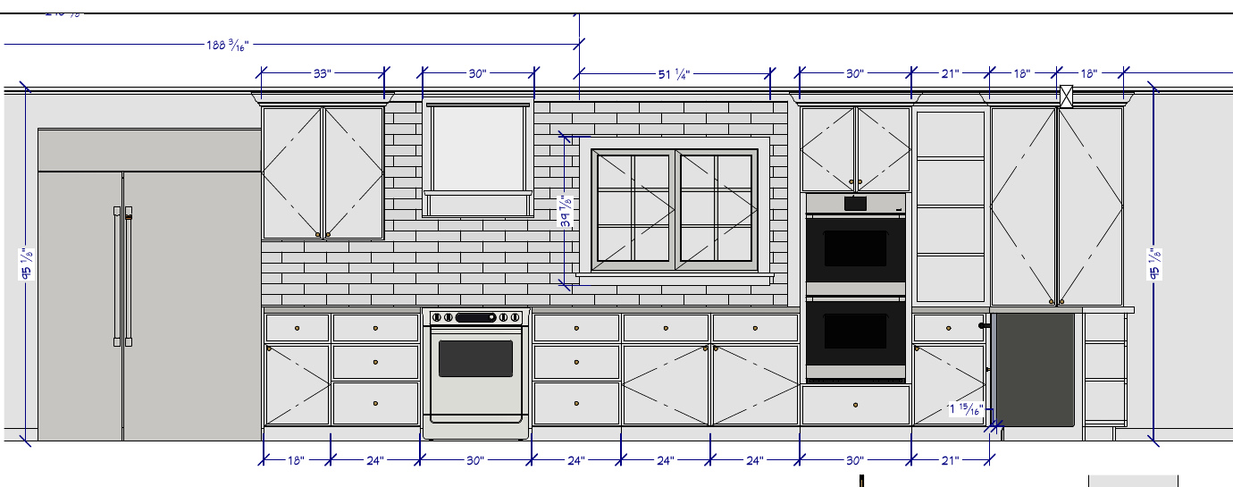
An elevation shows a wall straight on. Here, the cabinet widths and vertical dimensions are shown alongside the appliance openings and window. You can relate the measurements to an image of the actual cabinet arrangement.
That makes the conversation more specific: which cabinet sits beside the range, how the tall units relate to the window, and what dimensions the cabinetry must fit. The drawing supports both reviewing the design and coordinating the installation.
Color coding and notes that explain the work
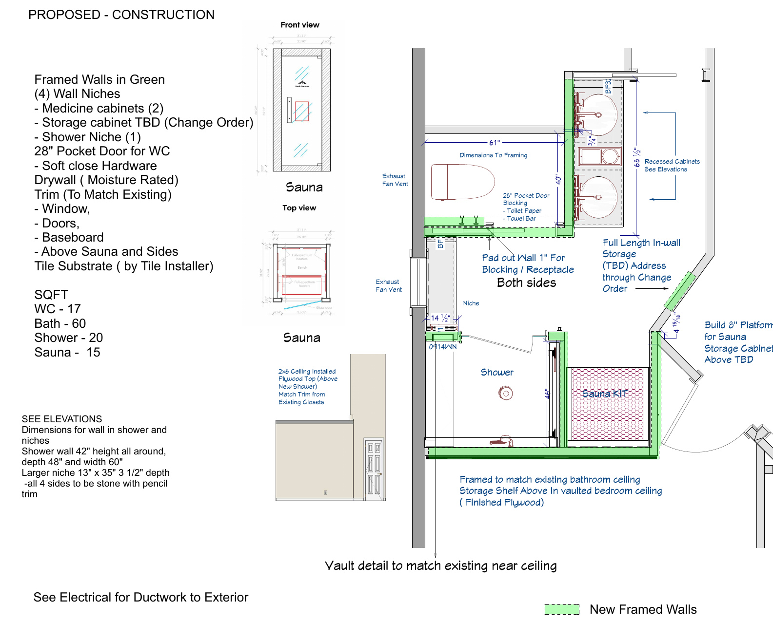
Look at how much information sits beside the layout: new framed walls, pocket-door requirements, blocking, recessed storage, ceiling details, and dimensions to framing. The sheet pairs the drawing with written instructions so the reader can connect a note to the relevant part of the room.
The useful part is the combination. Color helps distinguish elements, dimensions establish locations, and notes explain the intended work. None replaces checking the latest approved drawings and the conditions in the home.
A cabinet symbol becomes a specific cabinet
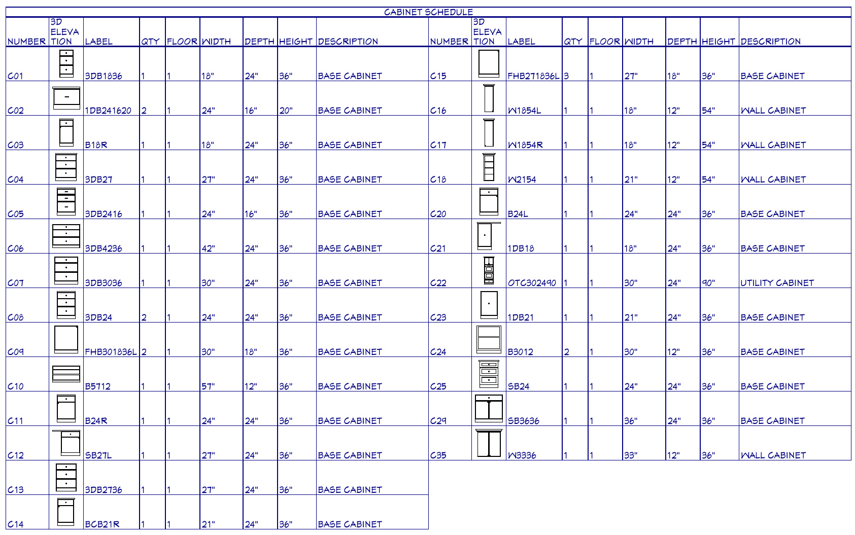
A drawing reference becomes more useful when it connects to a schedule. Instead of a generic cabinet shape, the team can look up the corresponding cabinet, its dimensions, quantity, and description. This is one way the plan supports coordination between design, ordering, and installation.
Where 3D views help—and where they stop
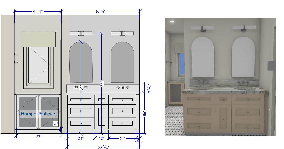
A 3D view makes it easier to picture cabinet proportions, the relationship between mirrors and lights, and the overall appearance. The dimensioned drawing provides technical information that the rendering cannot communicate on its own.
Our goal is to make the design easier to understand while retaining the information needed to carry out the work. A rendering is a visual aid; it does not replace construction details, specifications, engineering, or required approvals.
What to ask before paying for remodeling plans
Architects can also provide detailed construction sets, interior elevations, schedules, and construction-phase services. The AIA’s description of architectural services explains why the agreement and design stage matter. A floor-plan excerpt alone cannot establish what is included elsewhere in a complete set.
Ask to see a sample deliverable for a project like yours. Then ask:
- Will we receive overall layouts, dimensioned details, elevations, and schedules?
- Which selections will be resolved, and which will remain allowances or TBD items?
- Who checks that the plans, selections, and construction proposal agree?
- Who answers field questions and issues updated drawings?
- How will everyone know which revision is approved for the work?
Fine Home Contracting’s design-build process connects design development, selections, budget reviews, and planning for the contracted build. Your agreement should establish the deliverables and services for your particular project.
Planning an addition or major remodel in Connecticut?
Whether you are planning a home addition or a substantial renovation in Farmington, Avon, West Hartford, Burlington, or elsewhere in our service area, bring your goals and any existing drawings. We can discuss what is already defined and what needs to be developed before construction.
About the Author: David Perrotti